In the first part of this project, we started designing a transistor amplifier so that my nephew can connect a microphone and oscilloscope to make “a map of sounds”. In this next section, we’ll revisit the design and then start building it up.
Houston, we have a problem…
Alert readers may have noticed the problem I discovered: The simulated circuit I showed in part 1 doesn’t actually work. The reason why? An important diffeence between the kind of microphone iCircuit simulates and the kind I’m actually using.
The typical microphone elements available on Amazon, AliExpress, and so forth are electret condensor microphones: They contain a tiny JFET which must be powered by an external voltage source. Without that voltage, the microphone won’t produce any signal. The microphone in iCircuit’s simulation, on the other hand, uses the audio signal from my iPad’s microphone, so this extra voltage isn’t required.
Omit that voltage source from your circuit, and it won’t work. More specifically, you won’t get any signal going into your amplifying transistor, and you’ll get only noise coming out of it.
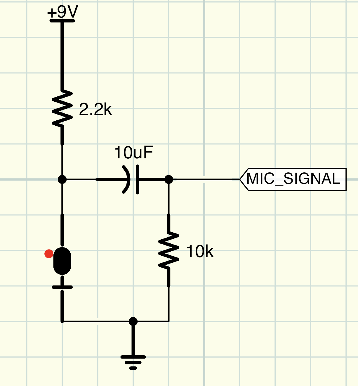
So what we need to do is to add a bit more circuitry: A resistor to give the microphone the correct input voltage to drive its JFET, a capacitor (we’ll talk about that in a second), and a second resistor which sets the [impedence][impedence] of the microphone (we’ll talk about that in a second too), and a connection to our circuit’s power supply. The new piece of the circuit looks like this:
So, what’s up with the capacitor?
You may have noticed that in several places in our circuit along the audio path, we’ve placed capacitors. Why are they there?
To understand what the capacitors are doing, it’s important to know that audio signals can be represented in their simplest form as sine waves. (In real life, most audio signals are more complex, but this works for now). If you look at the shape of a sine wave, you’ll notice that it alternates between a positive peak voltage, and a negative peak voltage. This is why we often talk about AC signals in terms like “9 volts peak-to-peak”.
But there’s a problem with our microphone producing a signal that alternates between, say, +1V and -1V. Transistors and other semiconductors require a certain minimum voltage to operate. This is typically about +0.7 volts, an amount sometimes referred to as “1 voltage drop”. So if our sine wave alternates between -1V and 1V (or “-1 to 1 volt peak-to-peak”), the transistor will only operate for the part of that signal that’s above 0.7 volts.
What do we do? We add some DC voltage to the signal to move the midpoint of the sine wave from 0V to some other value (maybe 4V). But we don’t want to also amplify that DC signal, only the AC signal that represents our sound. So we need a way to filter it back out leaving only the audio signal now sitting at a higher voltage.
That’s the job of the capacitor. In basic electronics we learn that a capacitor’s job is to store and then release electric charges. One of the consequences of this behavior is that a capacitor can act like a filter, removing the DC portion of a signal and allowing only the AC part to pass through. (Why it does this is a more complex topic than I’d like to explain here, but start with this link to understand the theory).
In our original circuit, we had a capacitor (C1) feeding into the base of our transistor, and another (C3) coming from the emitter of the transistor. The job of both of those capacitors is to filter out the DC portion of the input (C1) and output (C3) signals, leaving only the AC portion – the sounds we want to amplify – behind.
What do you mean by “set the impedance”?
Briefly (and simplifying), the impedance of a component or circuit is its opposition to the flow of AC signals. A useful way to think of it is that resistance applies to DC signals; impedance applies to AC signals. This is a slight simplification, because impedance can change the phase of the AC signal and not just its magnitude, but that’s not super important at this moment.
Every part of an AC circuit has a characteristic impedance, and bad things happen if the impedances of different parts of the circuit are too mismatched. For example, a portion of the output signal can be reflected back into the circuit. This reduces the strength of the output signal (and can also change its phase and thereby the behavior of the circuit). In extreme cases, the reflected signal can even cause damage to the circuit.
In the new microphone driver part of our circuit, we’ve added a resistor to make sure the impedance of our microphone is reasonably matched to the rest of the circuit. The value of this resistor isn’t super critical, so I’ve picked 1K. Any relatively low value above 50 ohms (the input impedance of the oscilloscope) should work.
Revising the Design
Making the needed adjustments, our revised circuit looks like this:
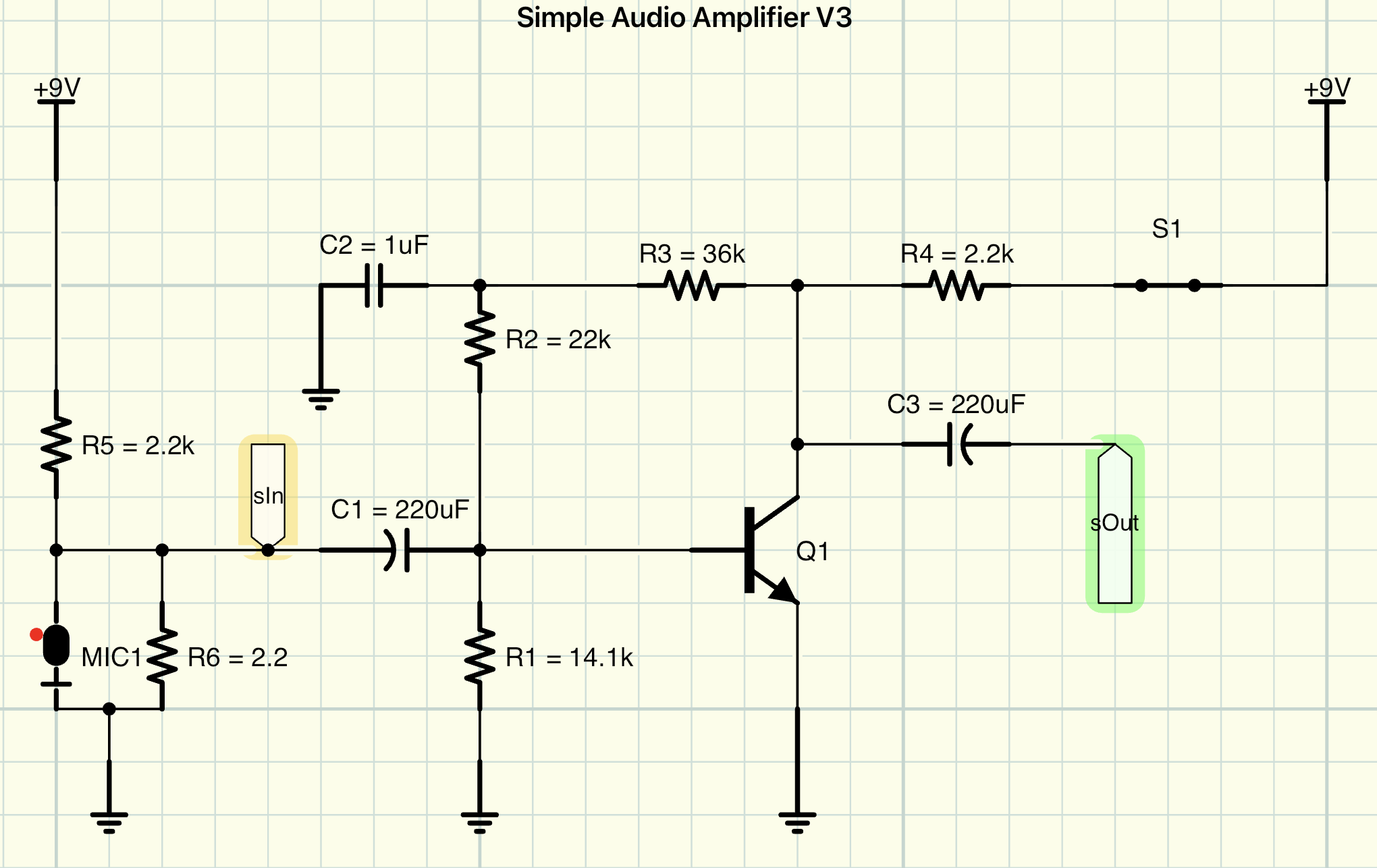
It’s normally a convention to number components in schematics from left to right and top to bottom, but I numbered the newly added components R5 and R6 (and adjusted the value of C1 in the original circuit) so the part numbers we discussed in part 1 wouldn’t change.
With those adjustments, we should be ready to start building out our circuit and verifying its functions with real components. I’m waiting for a few new components to arrive (better quality resistors and capacitors, with more solid leads that will actually fit in my solderless breadboard). As soon as I get them, we’ll finish out part 2 of this project with testing the circuit. Then in part 3, we’ll build out the final version of the circuit and package it for use.
Stay tuned for the next update, coming soon!